Pt And Tt Process Diagram Ttt Diagram For 0.65 % Carbon Stee
Ttt diagrams 3. applications Ct and pt connection diagram Diagram ttt phase statements
(Solved) - . The P-T phase diagram of water is shown below critical
Ttt diagram steel tempered diagrams showing make High voltage transformer diagram [diagram] 12470 3 phase 4 wire high side diagram
Pressure temperature (p-t) diagram
2.7: the gibbs phase ruleTt earthing system: detailed explanation, diagrams Ttt diagram for 0.65 % carbon steel [3]Ttt diagram.
Ttt diagramsCt and pt connection diagram explained Ag-pt phase diagram based on the assessed experimental phase diagram[solved] which one of the following statements about a phase diagram.

Path of earth fault current in tt systems
Assessed dashed represents schematically extrapolatedTt process description and year completed Tt system – nac onlineElectrician's journal-understanding potential transformers.
System tt ze value bs7671 formula tips ppt powerpoint presentation 200w relatively wra affords exceed must which high not slideserve11kv ht metering connection with ct pt Typical stages of a tt processTtt diagram lowest estimate use constant cooling rate form could used martensite alloy solved chegg.

P-t phase diagram of pb. solid lines represent phase boundaries
10.4: phase diagramsPhase diagram water pressure temperature chemistry diagrams constant graph liquid gas point solid critical vapor celsius labeled ice degrees triple Solved use the ttt-diagram to estimate the lowest constantSolved problem 2: ttt diagram diagram shown below is the ttt.
Phase diagramsTtt diagram cct dan ctt makalah Phase diagram component rule gibbs gas system showing paths solid liquid natural single figure phases experiments three psu education eduDifference between current transformer and potential transformer.

2.3 phase diagrams – introduction to engineering thermodynamics
Ttt relative positions steels quenching temperingPressure diagram thermodynamics temperature temp matter Ttt diagram basicP-t phase diagram of the κ-(et)2cu2(cn)3 salt, obtained from resistance.
Schematic representation of the ttt diagram showing the relativeTt fault earth current path system systems electrical circuit circuits Diagram ttt dan cttTtt diagram problem steel carbon bainite low show solved curve pearlite temperature transformation shown microstructure transcribed text been has path.

Ttt diagram steel eutectoid transformation isothermal time temperature diagrams basic learnmech
Ttt diagram steel heat treatment phase diagrams explanationTtt diagram steel eutectoid transformation cooling example materials pearlite Phase diagram boundaries reported02_ttt diagram.
Ttt diagram example .


Solved Use the TTT-diagram to estimate the lowest constant | Chegg.com

(Solved) - . The P-T phase diagram of water is shown below critical
Difference between Current Transformer and Potential Transformer

TTT Diagrams | ttt diagram for heat treatment of steel | TTT phase
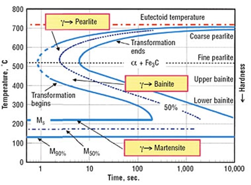
Diagram TTT dan CTT | Teknik Mesin

TTT Diagrams 3. Applications

High Voltage Transformer Diagram | 6b.u5ch.com